Proper selection of LED controllers and establishment of a reliable signal transmission system form the foundation of any lighting project. In this section, we covered how to choose between DMX and SPI controllers, the number of pixels or meters of light strips a single controller can support, strategies for long-distance signal transmission, best practices for cabling, and the critical concept of "common ground."
In LED lighting projects, correctly selecting an LED controller and building a reliable signal transmission system is the foundation of any lighting project. This article explains how to choose between a DMX controller and an SPI controller, how many pixels or meters of LED strips a single controller can drive, how to handle long-distance signal transmission, best practices for wiring, and the critical concept of “common ground,” helping you avoid common faults in LED lighting systems.
Section 1: Selection – DMX or SPI?
Q1: What is the difference between DMX controllers and SPI controllers? How should I choose?
DMX controllers follow the DMX512 protocol, a standard industrial-grade bus control method. Each signal line can control 512 channels (typically corresponding to 170 RGB LED fixtures or 512 single-color fixtures). The signal transmission is stable with strong anti-interference capabilities, making it suitable for large-scale projects, stage lighting, architectural lighting, and other scenarios requiring long-distance transmission and high reliability.
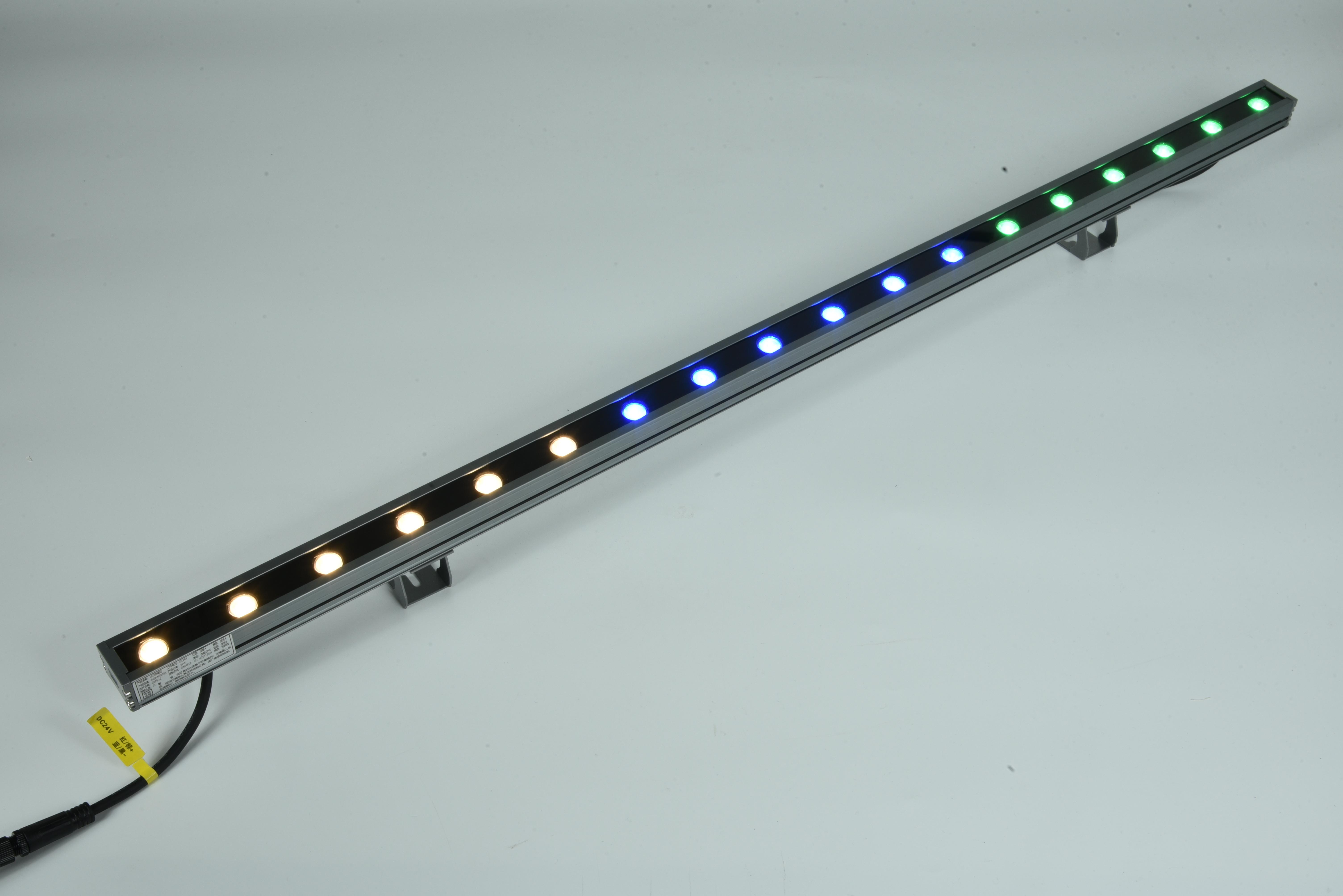
Seekway's CL30C Linear Light
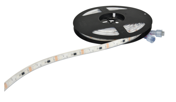
SPI controllers use serial communication protocols (such as WS2812B, SK6812, etc.), with each pixel having a built-in driver IC for “point-to-point” independent control. They are ideal for pixel LED strips, flexible screens, pixel point light sources, and other applications needing rich dynamic effects (such as chasing lights, flowing lights, and music synchronization).
Selection Suggestion: Choose DMX controllers for stable and reliable large-scale systems; choose SPI controllers for rich dynamic pixel effects when the project budget is limited.
Section 2: Load Capacity and Signal Transmission
Q2: How many meters of LED strips or how many pixels can one controller drive at most?
For SPI controllers, load capacity is usually calculated by the number of pixels (ICs) rather than simple “meters.” For example, a WS2812 LED strip has 60 pixels per meter; if a controller’s single port supports a maximum of 1024 pixels, it can theoretically drive about 17 meters, but due to voltage drop, power should be supplemented every 5 meters. For DMX controllers, calculation is based on channels: one DMX port supports up to 512 channels. When controlling RGB fixtures (3 channels each), it can drive approximately 170 fixtures (pixels). Please refer to the product specification sheet of the controller you are using for exact parameters.
Q3: What is the relationship between the controller’s “number of ports” and “load pixels”?
The number of ports refers to the physical signal output interfaces on the controller; each port can independently output one DMX or SPI signal. Load pixels refer to the maximum number of pixels each port can control. For example, an 8-port controller with 1024 pixels per port has a total load capacity of 8192 pixels. The more ports, the easier it is to achieve zoned control and wiring optimization—especially suitable for large projects or scenarios requiring independent editing by area.
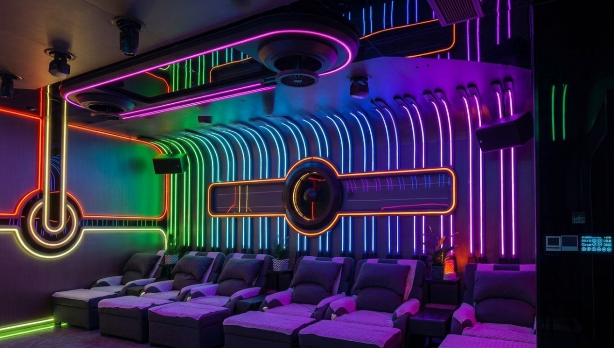
Light Up Bars with the Seekway A308 LED Controller
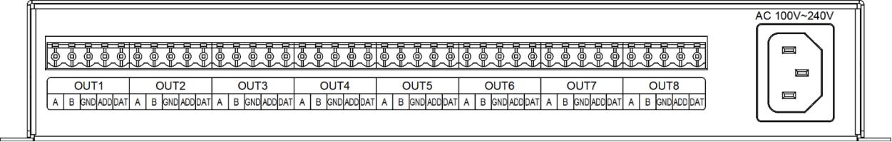
8 Ports of Controller
Q4: If my project distance is very long (over 50 meters), will the signal attenuate? How to solve signal transmission issues?
Yes, the signal will attenuate as transmission distance increases. For the DMX512 protocol, the standard recommended transmission distance is no more than 300 meters, but dedicated shielded twisted-pair cable must be used; for SPI protocol, it is usually recommended not to exceed 15-20 meters.
Solutions:
- Use signal amplifiers/repeaters and install one every recommended distance;
Seekway’s signal amplifiers
- For long-distance SPI transmission, use differential signal converters (converting single-ended signals to RS-422/RS-485 differential signals) to achieve stable transmission over hundreds of meters;
- Use fiber optic converters for ultra-long-distance transmission.
Q5: Do signal cables in projects need dedicated cables? Will using ordinary wires cause signal interference or frame loss?
Yes, it is required. The DMX512 protocol explicitly requires the use of shielded twisted-pair cable with a characteristic impedance of 120Ω (such as RVSP 2×0.5mm² or above) to ensure signal integrity. Using ordinary wires (such as RVV or BV wire) will cause impedance mismatch and poor anti-interference performance, easily leading to signal reflection, data frame loss, fixture flickering, or loss of control. For important projects, dedicated signal cables must be used, and termination resistors (120Ω) should be installed at the beginning and end of the line as needed to suppress reflections. We recommend using Cat5e network cable for signal transmission.
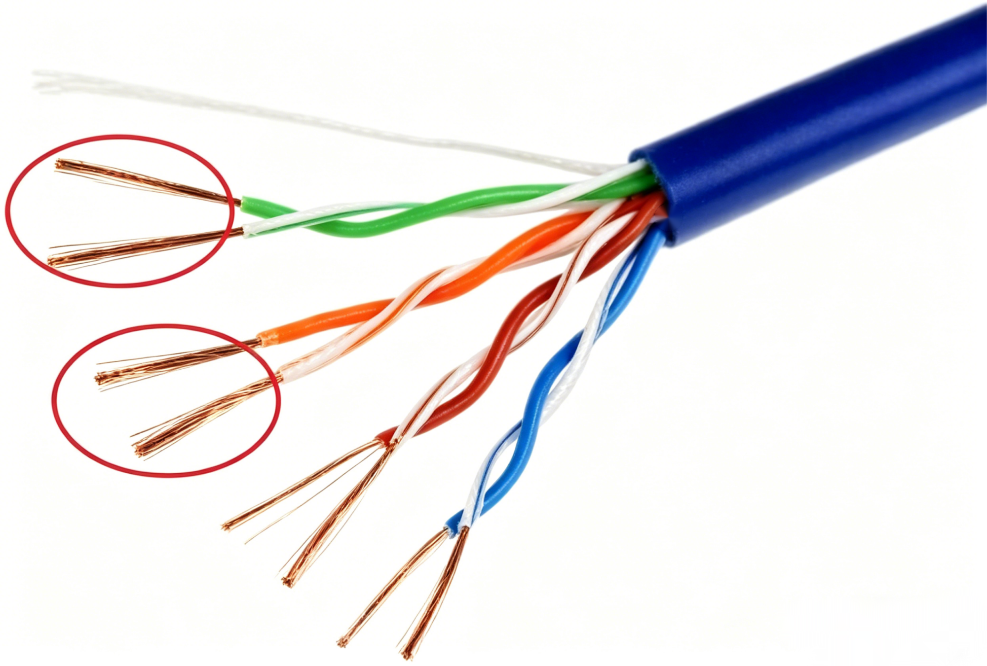
CAT5e Cable
Q6: What are “decoders” and “amplifiers”? When do they need to be additionally configured?
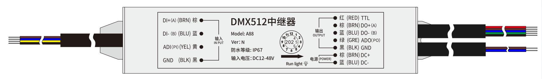
Decoders are mainly used to convert DMX512 signals into PWM signals to drive ordinary constant-voltage or constant-current LED fixtures (such as single-color LED strips or COB strips), allowing them to connect to a DMX control system.
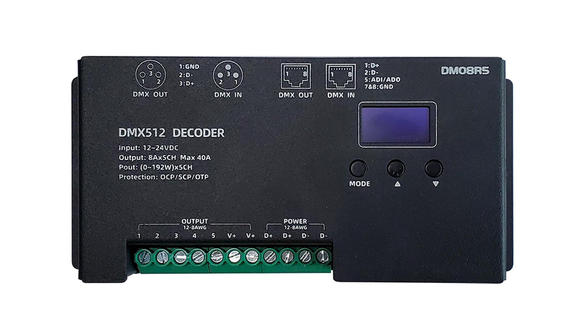
Seekway’s DMX512 Decoder
Amplifiers (signal amplifiers) are used to extend signal transmission distance. When the signal cable length exceeds the maximum distance recommended by the DMX protocol (about 300 meters) or when the SPI signal exceeds 15-20 meters, amplifiers must be installed to reshape the signal waveform and prevent attenuation that causes fixture flickering or loss of control.
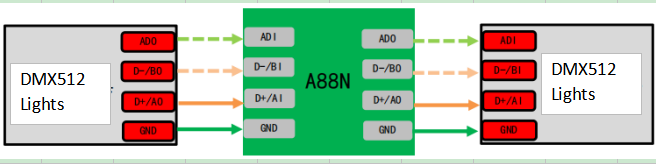
Connections bewteen amplifiers and DMX512 lights
Want to learn more about decoders and amplifiers? Click the link below to view the information.
https://www.seekway.com/collections/dmx-decoder
Section 3: Wiring and Installation
Q7: When installing the controller, what should be specially noted during preliminary wiring?
Three key points must be noted:
- Strong and weak current separation: Signal cables (DMX/SPI) must be routed in separate conduits from 220V strong current lines, maintaining at least 30 cm spacing to avoid electromagnetic interference;
- Cable selection: Use shielded twisted-pair cable for signal lines and select power cable diameter according to load power to avoid excessive voltage drop;
- Reserved space: The controller should be installed in a location that facilitates heat dissipation, maintenance, and is away from heat sources. It is recommended to reserve a weak-current box or dedicated control cabinet with maintenance access. The controller should also avoid high-temperature, humid, or strong electromagnetic interference environments. For large projects, standard rack-mount installation or outdoor waterproof enclosures are recommended.
Q8: What does “common ground” mean? Why can failing to share ground in DMX and SPI systems cause burnout or instability?
“Common ground” means connecting the controller’s signal ground (GND) with the negative pole of the fixtures/power supply to form a unified reference potential. If not grounded together, a potential difference exists between the controller and fixtures, which may cause signal level drift, communication failure, fixture flickering, and in severe cases, even burn out the controller or fixture input ports due to excessive potential difference.
Correct practice: The controller GND, power supply GND, and fixture GND must all be reliably connected together.
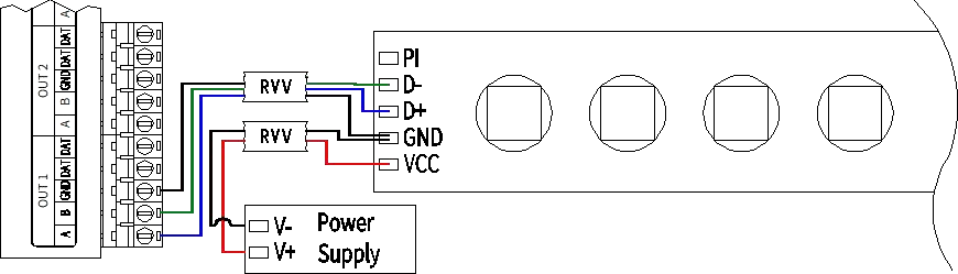
Connections between controllers and DMX lights
Summary
Correctly selecting the controller type, accurately calculating load capacity, using dedicated cables, and ensuring common ground are the first steps to building a reliable LED system. In the next article, we will delve into programming control, troubleshooting, and system architecture.


